Summary:
A ball bearing is an example of non rotate rolling element. These types of bearings are very common in all kinds of mac...
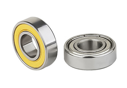
A ball bearing is an example of non rotate rolling element. These types of bearings are very common in all kinds of machinery, including cars, trains, engines and so on. These bearings have a different design and different applications. The main advantage of these bearings is that they are very light in weight and flexible, but also they provide high torque. The other big advantage of the ball bearing is that they can withstand large torque forces and high loading, which means that they can be used for heavy-duty and high-torque applications in heavy-duty machinery.
In some circumstances, two balls might need to be turned simultaneously. The design of such bearings involves one ball bearing pulling another ball bearing towards it or one bearing sliding between a set of balls, while another one is being spun around a spindle. In general, the larger the size of the set of balls, the lower the center-of-perch friction, while the smaller the size of the set of balls, the higher the center-of-perch friction. Thus, in order to provide high-speed operation and good energy conservation, it is advisable to use balls of different sizes.
Ball bearing designs consist of a rotor which is fixedly mounted on a shaft or a crank arm. The shaft and the crank arm are preferably made of steel to facilitate better thrust loads. Then, the design includes a number of balls of different shapes and sizes arranged in a quiver-like structure. The design of the ball bearing can be one of the following:
For high-speed operation and energy efficiency, most ball bearings are made with a single quiver-type journal. This arrangement reduces the amount of energy that is wasted as heat by conduction. Thus, the amount of heat is reduced and the amount of friction is increased. The quivers are then fitted into conical cutters which are used to transfer the rotary forces. The force applied to the quivers is primarily needed to help move the rollers. Thus, the rotary force generated during operation can help to reduce wastage of energy.
A secondary mechanism that is included in the manufacture of many ball bearing designs is the presence of radially-moving rollers. The rollers are fitted with the help of a series of gear boxes that help the rollers move radially. The number of such rollers required depends on the weight of the structure that requires to be carried out, the kind of rolling elements and the kind of bearing.
The figure 19 is one of the best-known design figures in the history of ball bearing designs. The figure 19 refers to the main gear case that is found at the hub or the reciprocating member. The figure 19 is comprised of a cylindrical outer casing and a series of circular inner rings. The inner ring is fitted around a cylindrical inner shaft that is known as a shaft seal; hence the term "ball bearing reaction forces."


 China Ring Bearings Suppliers